Embarking on the journey of building your first circuit can be both an exciting and educational experience. Whether you're a hobbyist, a student, or just curious about electronics, creating a basic circuit is a great way to understand the fundamentals of electrical engineering. This step-by-step guide will walk you through the necessary components and procedures to create your very first circuit.
Understanding the Basics
Before you dive into building, it’s essential to have a basic understanding of how circuits work. A circuit allows electricity to flow from a power source, through various components, and back to the source. Essential components include a power source like a battery, conductive paths such as wires, and various electronic components like resistors, capacitors, and LEDs.
Essential Components
-
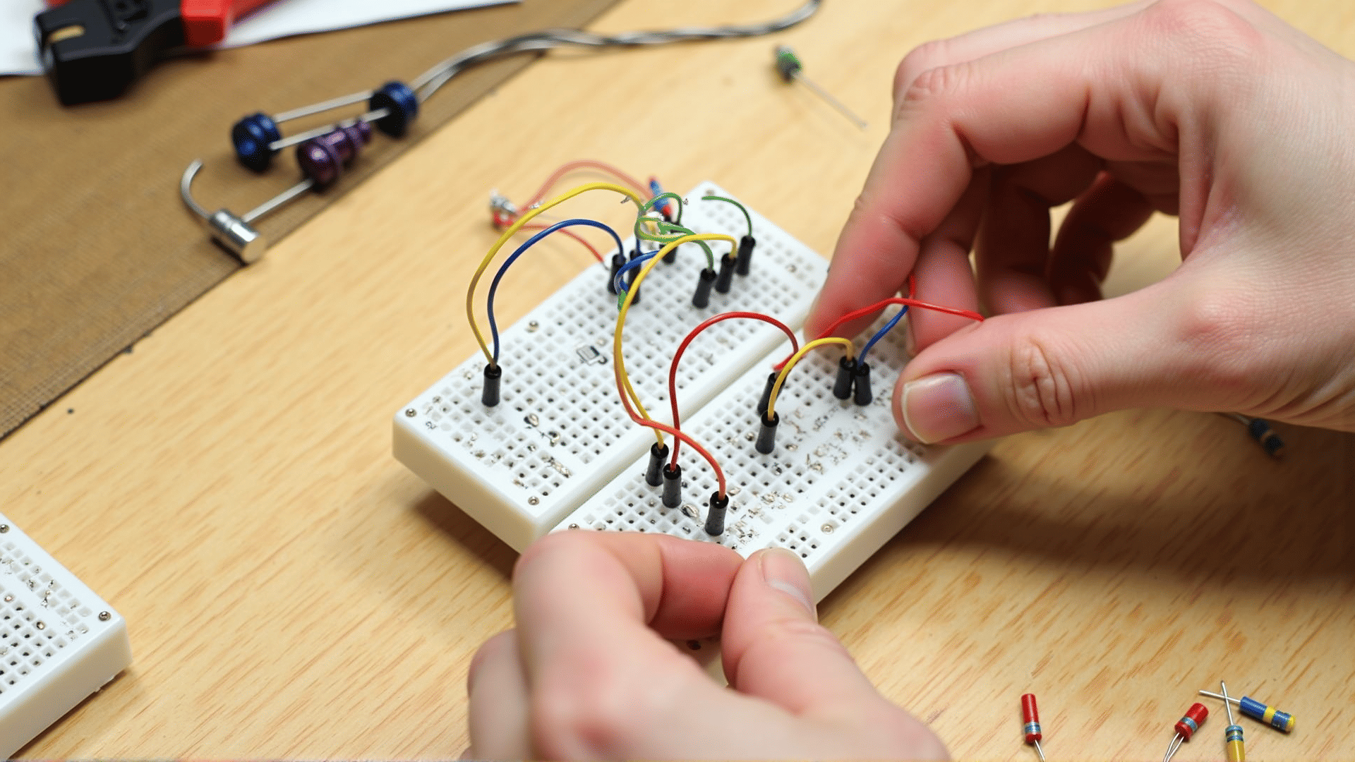
Breadboard: This is a construction base for prototyping circuits. It allows you to easily insert and remove components without soldering.
-
Power Source: A battery or power supply. A 9V battery is commonly used in simple circuits.
-
Wires: They connect various components in the circuit. Jumper wires are ideal for breadboards.
-
LED (Light Emitting Diode): A simple component that emits light when current flows through it.
-
Resistor: It limits the current flowing through the circuit, protecting components like LEDs from damage.
-
Switch (optional): Used to open and close the circuit without disconnecting parts.
Step-by-Step Guide
Step 1: Set Up the Breadboard
Begin by placing the breadboard on your work surface. The breadboard has numbered rows and columns of holes where you can insert components. The sets of holes in line are connected; familiarize yourself with the layout to ensure correct wiring.
Step 2: Connect the Power Source
Attach the battery to the breadboard using a battery connector. Connect the positive lead (usually red) to the breadboard's positive rail and the negative lead (usually black) to the negative rail.
Step 3: Insert the LED
Insert the LED into the breadboard. Remember that LEDs are polarized; the longer leg is the positive (anode) and should be connected to the positive rail. Insert the shorter leg (cathode) into the row where you plan to place the resistor.
Step 4: Add the Resistor
Insert one end of the resistor into the same row as the cathode of the LED and the other end to the negative rail. This will limit the current flowing through the LED, preventing it from burning out.
Step 5: Use Jumper Wires
Use jumper wires to complete the circuit. Connect a jumper wire from the power rail connected to the battery’s positive terminal to the anode of the LED. Use another wire to connect the resistor to the rail with the battery's negative terminal.
Step 6: Test the Circuit
Once everything is connected, your LED should light up when you connect the battery, indicating that the circuit is working. If it doesn’t light up, double-check the connections and ensure that the LED is inserted correctly with proper orientation.
Troubleshooting Tips
-
Check Polarities: Ensure that all components with polarity, like the LED, are connected correctly.
-
Secure Connections: Make sure that all components are firmly inserted into the breadboard holes.
-
Right Components: Verify that you're using the correct resistor value to prevent excessive current.
Building your first basic circuit is just the beginning of your exploration into electronics. By experimenting with more components and configurations, you can create increasingly complex and exciting projects. Enjoy the process and the knowledge gained along the way!